
Skip to content

Why Choose a CNC Wire Cut Machine?

Why Choose a Cnc Wire Cut Machine?

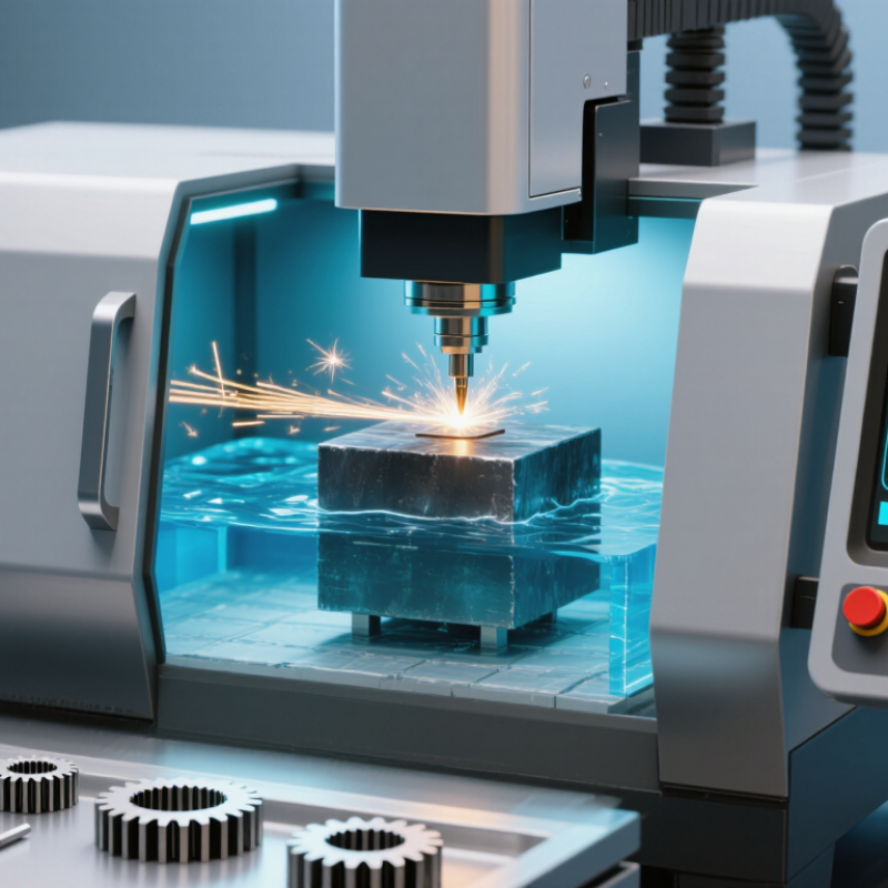
Choosing a Cnc Wire Cut Machine begins with understanding the workpiece, not the sales brochure. This technology uses a continuously moving wire electrode and controlled electrical discharges. It can cut hardened tool steel without applying heavy mechanical force. That matters when producing narrow slots, intricate profiles, and fine-pitch components.

Dr. John A. McGeough, a respected machining researcher, stated, “Wire electrical discharge machining removes material through controlled electrical discharges, rather than direct cutting force.” This principle explains its practical value. A 0.25-millimeter brass wire can follow a programmed contour through hardened steel. The workpiece remains submerged in dielectric fluid. Heat is localized, while the machine maintains precise servo control.

Accuracy is a major reason manufacturers choose this equipment. A Cnc Wire Cut Machine can reduce manual finishing on dies, punches, medical components, and precision fixtures. It also supports repeatable production when operators manage wire tension, flushing pressure, and offset compensation carefully. Small errors still matter. Poor flushing may leave recast layers or unstable cutting conditions.

The technology is not perfect. Cutting can be slower than conventional milling for simple shapes. Consumable wire adds operating cost. Programming quality also affects the final result. Still, when hardness, geometry, and dimensional control create difficult machining conditions, wire cutting becomes a dependable option. It offers controlled performance where ordinary tools may wear quickly or fail. That is the real question: not whether the machine is advanced, but whether its strengths match your production needs.
Why Choose a CNC Wire Cut Machine?

Define CNC Wire EDM: 0.10–0.30 mm Wire and ±0.005 mm Accuracy

Why choose a CNC wire cut machine? The answer often begins with control, not speed. CNC wire EDM uses a continuously moving metal wire, commonly 0.10–0.30 mm in diameter, to remove material through controlled electrical discharges. This narrow cutting path suits hardened steel, carbide, and intricate profiles that conventional tools may distort.

A stated accuracy of ±0.005 mm equals five micrometres. That is a serious target. However, it should not be confused with guaranteed part accuracy under every condition. ISO 230-2:2014 recommends checking positioning performance through measured movement and repeatability. In practice, operators also monitor dielectric temperature, wire tension, flushing pressure, and thermal drift. Small changes matter.

Industry data supports the demand for precision manufacturing. Grand View Research has reported continued growth in the global electrical discharge machining market, driven by aerospace, medical, and automotive applications. Those sectors increasingly require repeatable micro-features and complex internal contours. A 0.20 mm wire can produce a fine slot, but thicker wire may improve stability and cutting efficiency. That trade-off is easy to overlook.

Real workshops reveal another truth. ±0.005 mm is achievable only with disciplined setup, calibration, and inspection. A warm machine can quietly move the result. So can poor flushing. CNC control reduces human variation, but it does not remove engineering judgment.

Why Choose a CNC Wire Cut Machine?

CNC Wire EDM uses a continuously fed wire electrode, commonly available from 0.10 to 0.30 mm in diameter, to produce precise cuts through electrically conductive materials. The chart compares representative wire diameters with a ±0.005 mm accuracy reference.

Compare Cutting Capability: Up to 500 mm Thick Hardened Materials

Why Choose a CNC Wire Cut Machine?

Compare Cutting Capability: Up to 500 mm Thick Hardened Materials

When a job involves hardened steel, tool steel, or thick alloy plate, conventional milling can struggle. A CNC wire cut machine removes material through controlled electrical discharges. The wire does not push against the workpiece. This reduces cutting force and helps protect delicate profiles. Suitable systems can process materials up to 500 mm thick. That depth is practical, not automatic.

At this thickness, flushing becomes critical. Water must reach the cutting gap and carry away particles effectively. Poor flushing may cause unstable sparking, slow cutting, or wire breakage. Operators also check workpiece alignment, wire tension, and electrical settings before production. A stable setup can create narrow slots, sharp internal corners, and repeatable contours. Hardened material remains firm throughout the process. Heat-affected damage is usually limited, but it should still be inspected.

In real workshops, the advertised maximum is only one part of the decision. Material grade, starting hole design, taper requirements, and surface finish affect the result. A 500 mm block may need multiple passes and extended cutting time. It may also require careful support to prevent movement. That detail is easy to overlook. Test cuts and dimensional checks provide stronger evidence than specifications alone. I would not select a machine from thickness capacity alone; service access, control stability, and operator training matter just as much.

Measure Productivity: Typical Cutting Rates of 50–300 mm²/min

Why Choose a CNC Wire Cut Machine?

Measure productivity by cutting area, not wire travel alone. Typical wire EDM cutting rates range from 50 to 300 mm²/min, depending on material, thickness, accuracy, and flushing quality. A 2023 review in CIRP Journal of Manufacturing Science and Technology identifies discharge energy, dielectric flow, and thermal conditions as major productivity factors.

Consider a 100 × 50 mm profile. Its cutting area is 5,000 mm². At 200 mm²/min, the ideal cutting time is about 25 minutes.

Real production takes longer. Setup, threading, corner control, skim passes, and inspection matter. The figure is not a promise.

A 2022 review in the Journal of Manufacturing Processes reports that harder alloys often require slower parameters to control wire breakage and surface damage.

In practical workshops, 50–120 mm²/min may suit thick or difficult materials. Stable workpieces can approach 200–300 mm²/min under favorable conditions.

I have seen operators chase the upper rate and lose time through rework. That is the uncomfortable lesson.

The U.S. Department of Energy’s manufacturing efficiency guidance also treats idle time and repeated processing as important productivity losses. Therefore, compare complete cycle time, not only the machine display. Record cutting rate, wire consumption, surface roughness, and rejected parts for each material. Small errors become expensive.

Evaluate Automation: CNC Control, Automatic Threading, and Unattended Cutting

Why Choose a CNC Wire Cut Machine?

Automation deserves careful evaluation, not optimistic promises. CNC control converts a digital drawing into repeatable cutting movements, while programmable settings manage speed, power, flushing, and corner accuracy. A stable control system can reduce manual adjustments during long production runs. Still, the result depends on accurate geometry, suitable wire settings, and disciplined setup. Automation cannot correct a poor drawing.

Automatic threading adds practical value between jobs. After a wire break, the system can thread the wire through a narrow opening without stopping for extended manual intervention. This matters when cutting hardened tool steel or intricate profiles with small internal features. The operator should still check threading alignment, nozzle clearance, and wire tension. Small errors can create large finish problems.

Unattended cutting is another reason to consider CNC wire technology. A properly prepared program may run overnight, using sensors and alarms to monitor wire breaks, fluid conditions, and abnormal movement. That can improve machine utilization and reduce repetitive supervision. However, “unattended” does not mean risk-free. Workholding, fire prevention, tank cleanliness, and recovery procedures need verification before leaving the machine. Automation is not magic. A missed inspection can turn a productive shift into expensive rework. In real workshops, the best results come from combining reliable CNC functions with clear checklists and trained judgment.

Assess Applications: Dies, Molds, Carbide, and Complex Tapered Profiles

Why Choose a CNC Wire Cut Machine?

A CNC wire cut machine suits dies and molds when geometry matters more than cutting speed. It produces narrow kerfs, sharp internal corners, and repeatable profiles without direct cutting pressure. That matters for hardened tool steel, where conventional milling may cause vibration or tool wear. Carbide is another strong application. The U.S. Geological Survey reported about 78,000 metric tons of mined tungsten production in 2023. Much of this material supports carbide manufacturing, where controlled electrical discharge can reduce mechanical stress. Still, wire cutting is not automatically faster. Thick sections, difficult flushing, and multiple skim passes can extend cycle time.

Complex tapered profiles show the machine’s real value. A four-axis system can control upper and lower guide offsets, creating angled punches, nozzles, and mold inserts. The result depends on wire tension, dielectric condition, workpiece height, and taper compensation. ISO 230-2 testing principles emphasize checking positioning accuracy rather than trusting nominal coordinates alone. A profile can look correct on screen and still drift at the workpiece.

Tips: Measure the actual taper on a trial piece. Record corner accuracy, surface roughness, and cutting time. For carbide, confirm electrical settings with the material supplier’s technical data. A practical mistake is using one parameter set for every thickness. It saves setup time, but it can weaken accuracy and surface quality.

Why Choose a CNC Wire Cut Machine? - Assess Applications: Dies, Molds, Carbide, and Complex Tapered Profiles

Application Typical Workpiece Materials Why Wire EDM Is Suitable Common Geometry Typical Accuracy Range* Surface Finish Potential* Important Considerations
Precision Dies Tool steel, hardened steel, carbide, and conductive composite materials Cuts hardened materials without applying conventional cutting forces, reducing the need for post-hardening machining Punches, die openings, stripper plates, narrow slots, and fine blanking profiles Approximately ±0.0025–0.010 mm under controlled conditions Approximately Ra 0.2–1.6 µm, depending on cutting passes and process settings Workpiece must be electrically conductive; wire diameter, flushing, thermal stability, and multiple skim cuts affect results
Mold Components Hardened tool steel, stainless steel, conductive mold alloys, and graphite electrodes Produces accurate internal profiles and sharp details after heat treatment, with minimal mechanical distortion Cavity inserts, core components, ejector plates, slides, vent slots, and intricate contours Approximately ±0.005–0.015 mm for many production applications Approximately Ra 0.4–1.6 µm; finer finishes generally require additional skim cuts Large or thick mold components require stable dielectric flushing and careful control of workpiece alignment
Conductive Carbide Electrical-discharge-machinable cemented carbide and other electrically conductive hard materials Machines extreme hardness without direct contact between the cutting wire and the workpiece Wear inserts, carbide punches, forming tools, precision nozzles, and small slots Approximately ±0.005–0.015 mm, subject to carbide grade, thickness, and machine condition Approximately Ra 0.3–1.6 µm with suitable flushing and finishing passes Electrical conductivity and binder composition influence cutting stability; brittle edges require controlled energy and flushing
Complex Tapered Profiles Tool steel, hardened steel, carbide, titanium alloys, and other conductive metals Independent upper and lower wire-guide movement enables programmed taper and changing-profile cuts Tapered punches, turbine features, angled cores, sloped inserts, and 3D-contoured parts Approximately ±0.010–0.030 mm on many tapered features, depending on height and angle Approximately Ra 0.4–1.6 µm, with geometry and flushing affecting the final surface Maximum taper angle, workpiece height, wire-guide travel, and collision clearance are machine-specific
Micro-Features and Fine Slots Hardened steels, stainless steels, nickel alloys, and conductive carbide Small wire diameters and non-contact cutting allow narrow slots, small radii, and delicate profiles Fine apertures, miniature punches, narrow channels, and precision indexing features Approximately ±0.005–0.020 mm, depending on feature size and material thickness Approximately Ra 0.3–1.6 µm with optimized pulse parameters and finishing passes Very small features are sensitive to wire deflection, debris removal, thermal conditions, and programming quality
Thick Precision Parts Hardened tool steels, stainless steels, nickel-based alloys, and conductive superalloys Can cut through substantial material thicknesses while maintaining a narrow kerf and avoiding tool wear from mechanical contact Large die plates, thick inserts, precision gears, and complex through-features Approximately ±0.010–0.030 mm, with accuracy influenced strongly by height and flushing Approximately Ra 0.6–2.0 µm, depending on thickness and the number of finishing passes Cutting speed and straightness may decline as thickness increases; adequate flushing and workholding are essential

*The accuracy and surface-finish values are representative industry ranges, not guaranteed specifications. Actual results depend on machine design, wire diameter, workpiece thickness, material condition, flushing, thermal control, programming, and the number of finishing passes.